

 Nederlands
Electronic circuits
Rain alarm
This circuit gives out an alarm when its sensor is wetted by water.
A 555 astable multivibrator is used here which gives a tone of about 1kHz upon detecting water.
The sensor when wetted by water completes the circuit and makes the 555 oscillate at about 1kHz.
A 555 astable multivibrator is used here which gives a tone of about 1kHz upon detecting water.
The sensor when wetted by water completes the circuit and makes the 555 oscillate at about 1kHz.
The sensor is also shown in the circuit diagram.
It has to placed making an angle of about 30 - 45 degrees to the ground. This makes the rain water to flow through it to the ground and prevents the alarm from going on due to the stored water on the sensor.
The metal used to make the sensor has to be aluminium and not copper. This is because copper forms a blue oxide on its layer on prolonged exposure to moisture and has to be cleaned regularly.
The aluminium foils may be secured to the wooden / plastic board via epoxy adhesive or small screws.
The contact X and Y from the sensor may be obtained by small crocodile clips or you may use screws.

Burglar alarm
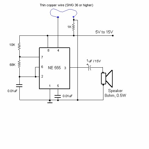
This circuit utilising a 555 timer IC can be used as an alarm system to prevent the theft of your luggage, burglars breaking into your house etc. The alarms goes ON when a thin wire, usually as thin as a hair is broken.
The circuit is straightforward. It uses a 555 IC wired as an astable multivibrator to produce a tone of frequency of about 1kHz which gives out a shrill noise to scare away the burglar.
The wire used to set off the alarm can be made of a thin copper wire like SWG 36 or higher.
You can even use single strands of copper form a power cable.
The circuit operates on a wide range of voltages from 5V to 15V.
The speaker and the circuit could be housed inside a tin can with holes drilled on the speaker side for the sound to come out.
The speaker and the circuit could be housed inside a tin can with holes drilled on the speaker side for the sound to come out.
Power supply failure alarm
Most of the power supply failure indicator circuits need a separate power supply for themselves. But the alarm circuit presented here needs no additional supply source. It employs an electrolytic capacitor to store adequate charge, to feed power to the alarm circuit which sounds an alarm for a reasonable duration when the supply fails.
This circuit can be used as an alarm for power supplies in the range of 5V to 15V.
To calibrate the circuit, first connect the power supply (5 to 15V) then vary the potentiometer VR1 until the buzzer goes from on to off.
Whenever the supply fails, resistor R2 pulls the base of transistor low and saturates it, turning the buzzer ON

A simple electronic buzzer
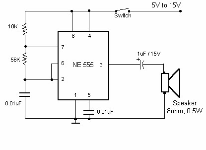
This very simple circuit just uses a couple of resistors, a capacitor and the easily available 555 timer IC.
The 555 is setup as an astable multivibrator operating at a frequency of about 1kHz that produces a shrill noise when switched on. The frequency can be changed by varying the 10K resistor.
The 555 is setup as an astable multivibrator operating at a frequency of about 1kHz that produces a shrill noise when switched on. The frequency can be changed by varying the 10K resistor.
Water indicator with alarm
This circuit not only indicates the amount of water present in the overhead tank but also gives an alarm when the tank is full.
The circuit uses the widely available CD4066, bilateral switch CMOS IC to indicate the water level through LEDs.
When the water is empty the wires in the tank are open circuited and the 180K resistors pulls the switch low hence opening the switch and LEDs are OFF. As the water starts filling up, first the wire in the tank connected to S1 and the + supply are shorted by water. This closes the switch S1 and turns the LED1 ON. As the water continues to fill the tank, the LEDs2 , 3 and 4 light up gradually.
The no. of levels of indication can be increased to 8 if 2 CD4066 ICs are used in a similar fashion.
When the water is full, the base of the transistor BC148 is pulled high by the water and this saturates the transistor, turning the buzzer ON. The SPST switch has to be opened to turn the buzzer OFF.
Remember to turn the switch ON while pumping water otherwise the buzzer will not sound!
Remember to turn the switch ON while pumping water otherwise the buzzer will not sound!

4 in 1 burglar alarm
In this circuit, the alarm will be switched on under the following four different conditions: 1. When light falls on LDR1 (at the entry to the premises). 2. When light falling on LDR2 is obstructed. 3. When door switches are opened or a wire is broken. 4. When a handle is touched. The light dependent resistor LDR1 should be placed in darkness near the door lock or handle etc. If an intruder flashes his torch, its light will fall on LDR1, reducing the voltage drop across it and so also the voltage applied to trigger 1 (pin 6) of IC1. Thus transistor T2 will get forward biased and relay RL1 energise and operate the alarm. Sensitivity of LDR1 can be adjusted by varying preset VR1. LDR2 may be placed on one side of a corridor such that the beam of light from a light source always falls on it. When an intruder passes through the corridor, his shadow falls on LDR2. As a result voltage drop across LDR2 increases and pin 8 of IC1 goes low while output pin 9 of IC1 goes high. Transistor T2 gets switched on and the relay operates to set the alarm. The sensitivity of LDR2 can be adjusted by varying potentiometer VR2. A long but very thin wire may be connected between the points A and B or C and D across a window or a door. This long wire may even be used to lock or tie something. If anyone cuts or breaks this wire, the alarm will be switched on as pin 8 or 6 will go low. In place of the wire between points A and B or C and D door switches can be connected. These switches should be fixed on the door in such a way that when the door is closed the switch gets closed and when the door is open the switch remains open. If the switches or wire, are not used between these points, the points should be shorted. With the help of a wire, connect the touch point (P) with the handle of a door or some other suitable object made of conducting material. When one touches this handle or the other connected object, pin 6 of IC1 goes ‘low’. So the alarm and the relay gets switched on. Remember that the object connected to this touch point should be well insulated from ground. For good touch action, potentiometer VR3 should be properly adjusted. If potentiometer VR3 tapping is held more towards ground, the alarm will get switched on even without touching. In such a situation, the tapping should be raised. But the tapping point should not be raised too much as the touch action would then vanish. When you vary potentiometer VR1, re-adjust the sensitivity of the touch point with the help of potentiometer VR3 properly. If the alarm has a voltage rating of other than 6V (more than 6V), or if it draws a high current (more than 150 mA), connect it through the relay points as shown by the dotted lines. As a burglar alarm, battery backup is necessary for this circuit. Note: Electric sparking in the vicinity of this circuit may cause false triggering of the circuit. To avoid this adjust potentiometer VR3 properly.

Light flasher
This is basically a flasher circuit modified to turn on and off a bulb instead of a LED. It uses a 555 timer IC working as an astable multivibrator. The flashing rate can be varied from very fast to a maximum of once in 1.5 sec by varying the preset VR1.
The ON time of the circuit is given by:
TON= 0.69xC1x(R1 + VR1) second
and the OFF time is:
TOFF= 0.69xC1xVR1 second
You can increase the value of C1 to 100uF to get a slower flashing rate of upto once in 10 sec.
The ON time of the circuit is given by:
TON= 0.69xC1x(R1 + VR1) second
and the OFF time is:
TOFF= 0.69xC1xVR1 second
You can increase the value of C1 to 100uF to get a slower flashing rate of upto once in 10 sec.

Daylight alarm
The circuit presented here wakes you up with a loud alarm at the break of the daylight. Once again the 555 timer is used here. It is working as an astable multivibrator at a frequency of about 1kHz.
The circuit's operation can be explained as follows:
When no light falls on the LDR, the transistor is pulled high by the variable resistor. Hence the transistor is OFF and the reset pin of the 555 is pulled low. Due the this the 555 is reset.
When light falls on the LDR, its resistance decreases and pulls the base of the transistor low hence turning it ON. This pulls the reset pin 4 of the 555 high and hence enables the 555 oscillator and a sound is produced by the speaker.
The variable 100K resistor has to be adjusted to set the light intensity that triggers the alarm.

Siren generator
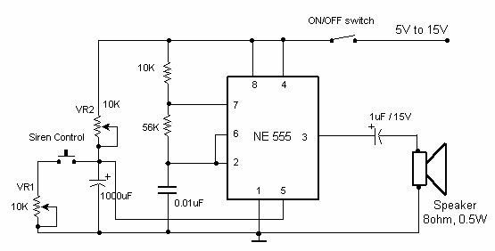
This circuit produces a sound similar to a factory siren.
It makes use of a 555 timer Ic used as an astable multivibrator of a center frequency of about 300Hz.
The frequency is controlled by the pin 5 of the IC. When the supply is switched ON, the capacitor charges slowly and this alters the voltage at pin 5 of the IC hence the frequenct gradually increases.
After the capacitor is fully charged, the frequency no longer increases. Now when the push button siren control switch is held depressed, the capacitor discharges and the siren frequency also decreases.
The presets VR1 and VR2 should be adjusted for optimum performance.
Police sirene
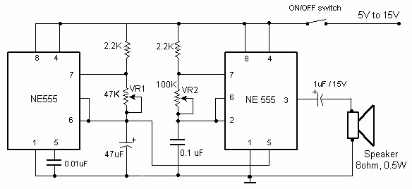
This circuit produces a sound similar to the police siren.
It makes use of two 555 timer ICs used as astable multivibrators. The frequency is controlled by the pin 5 of the IC.
The first IC (left) is wired to work around 1Hz. The 47uF capacitor is charged and discharged periodically and the voltage across it gradually increases and decreases periodically.
This varying voltage modulates the frequency of the 2nd IC. This process repeats and what you hear is the sound remarkably similar to the police siren.
Two presets VR1 and VR2 are provided to vary the siren period of repetition and the tone of the siren.
By varying VR1 you can set how fast the siren changes from high freq. to low freq.
VR2 sets the siren frequency. Adjust VR1 and VR2 to suit your taste.
Big Ben sound
This circuit produces the famous Big Ben sound. It produces the "ding dong" sound when switched ON.
Basically the circuit alternates between two frequencies which are adjustable. This produces the "ding-dong" sound.
The first IC(left) oscillates at about 1Hz. The second IC's tone is modulated by the changing voltage at the output of the first IC.
Basically the circuit alternates between two frequencies which are adjustable. This produces the "ding-dong" sound.
The first IC(left) oscillates at about 1Hz. The second IC's tone is modulated by the changing voltage at the output of the first IC.
The first IC determines how fast the changeover from one frequency to the other takes place and second IC determines the tone of the final output.
By varying the VR1, the changeover rate can be adjusted. By varying VR2 the tone can be adjusted.
By varying the VR1, the changeover rate can be adjusted. By varying VR2 the tone can be adjusted.

Audio level meter
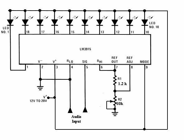
This circuit uses just one IC and a very few number of external components. It displays the audio level in terms of 10 LEDs. The input voltage can vary from 12V to 20V, but suggested voltage is 12V.
The LM3915 is a monolithic integrated circuit that senses analog voltage levels and drives ten LEDs providing a logarithmic 3 dB/step analog display. LED current drive is regulated and programmable, eliminating the need for current limiting resistors.
The IC contains an adjustable voltage reference and an accurate ten-step voltage divider. The high-impedance input buffer accepts signals down to ground and up to within 1.5V of the positive supply. Further, it needs no protection against inputs of ±35V. The input buffer drives 10 individual comparators referenced to the precision divider. Accuracy is typically better than 1 dB.
Light fader
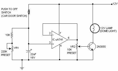
This unique circuit makes your dome light look cool. Usually when the car door is closed, the dome light just goes OFF. With this circuit, you can have our dome light fade slowly in brightness and finally go OFF. This slow dimming of the light gives a very good feeling at night. It looks very romantic!
The circuit can be explained as follows: When the car door is open, the push to off switch of the door is ON and hence it charges the 22uF capacitor fully. The opamp is acting as a voltage follower and its output is same as the voltage across the capacitor, which is 12V when the capacitor is fully charged. Due to a high voltage at the output of the IC, the transistor saturates, turning ON the bulb to full brightness.
The circuit can be explained as follows: When the car door is open, the push to off switch of the door is ON and hence it charges the 22uF capacitor fully. The opamp is acting as a voltage follower and its output is same as the voltage across the capacitor, which is 12V when the capacitor is fully charged. Due to a high voltage at the output of the IC, the transistor saturates, turning ON the bulb to full brightness.
Now when the door is closed, the door switch is pushed in and hence the switch goes OFF. When the switch is OFF, the capacitor starts discharging slowly through VR1 and the 10K resistor and the voltage across it decreases slowly. Hence at the output of IC 741 also the voltage decreases gradually, hence decreasing the base current to the transistor. This produces a slowly decreasing current through the bulb and the bulb fades out and finally when the capacitor is fully discharged, the bulb goes OFF.
After building the circuit, with the push-to-off switch in ON position (not pushed in) i.e. the car door open, adjust the preset VR2 to the required initial brightness of the bulb. Then push the switch in to turn it OFF(or close the door) and adjust VR1 for the time to bring the bulb from full brightness to OFF.
I would suggest you set VR1 and VR2 to their maximum values.
Simple analog to digital converter
Normally analogue-to-digital con-verter (ADC) needs interfacing through a microprocessor to convert analogue data into digital format. This requires hardware and necessary software, resulting in increased complexity and hence the total cost.
The circuit of A-to-D converter shown here is configured around ADC 0808, avoiding the use of a microprocessor. The ADC 0808 is an 8-bit A-to-D converter, having data lines D0-D7. It works on the principle of successive approximation. It has a total of eight analogue input channels, out of which any one can be selected using address lines A, B and C. Here, in this case, input channel IN0 is selected by grounding A, B and C address lines.
Usually the control signals EOC (end of conversion), SC (start conversion), ALE (address latch enable) and OE (output enable) are interfaced by means of a microprocessor. However, the circuit shown here is built to operate in its continuous mode without using any microprocessor. Therefore the input control signals ALE and OE, being active-high, are tied to Vcc (+5 volts). The input control signal SC, being active-low, initiates start of conversion at falling edge of the pulse, whereas the output signal EOC becomes high after completion of digitisation. This EOC output is coupled to SC input, where falling edge of EOC output acts as SC input to direct the ADC to start the conversion.
As the conversion starts, EOC signal goes high. At next clock pulse EOC output again goes low, and hence SC is enabled to start the next conversion. Thus, it provides continuous 8-bit digital output corresponding to instantaneous value of analogue input. The maximum level of analogue input voltage should be appropriately scaled down below positive reference (+5V) level.
The ADC 0808 IC requires clock signal of typically 550 kHz, which can be easily derived from an astable multivibrator constructed using 7404 inverter gates. In order to visualise the digital output, the row of eight LEDs (LED1 through LED8) have been used, wherein each LED is connected to respective data lines D0 through D7. Since ADC works in the continuous mode, it displays digital output as soon as analogue input is applied. The decimal equivalent digital output value D for a given analogue input voltage Vin can be calculated from the relationship

Infrared remote jammer
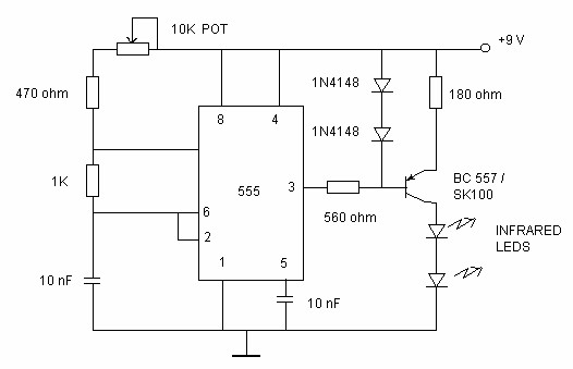
Just point this small device at the TV and the remote gets jammed . The circuit is self explanatory . 555 is wired as an astable multivibrator for a frequency of nearly 38 kHz. This is the frequency at which most of the modern TVs receive the IR beam . The transistor acts as a current source supplying roughly 25mA to the infra red LEDs. To increase the range of the circuit simply decrease the value of the 180 ohm resistor to not less than 100 ohm.
It is required to adjust the 10K potentiometer while pointing the device at your TV to block the IR rays from the remote. This can be done by trial and error until the remote no longer responds.
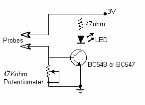
Enough water tester
This simple device checks if there is water in a pot plant. You stick the two probes(paperclips)into the pot plant and if the LED lights, it means there is water in the pot plant.
You need to adjust the 47k potentiometer to set the level at which the LED goes on.
Light flasher
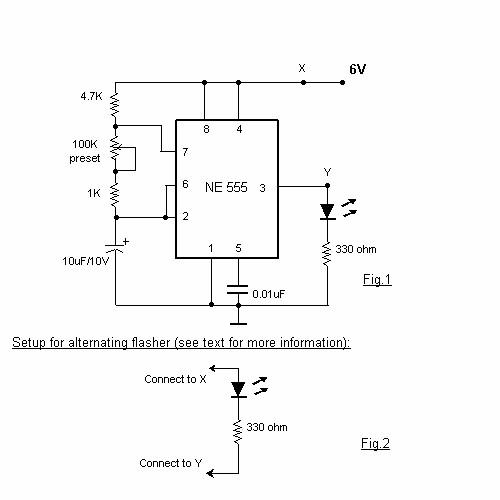
This is a very basic circuit for flashing one or more LEDS and also to alternately flash one or more LEDs.
It uses a 555 timer setup as an astable multivibrator with a variable frequency.
With the preset at its max. the flashing rate of the LED is about 1/2 a second. It can be increased by increasing the value of the capacitor from 10uF to a higher value. For example if it is increased to 22uF the flashing rate becomes 1 second.
There is also provision to convert it into an alternating flasher. You just have to connect a LED and a 330ohm as shown in Fig.2 to the points X and Y of Fig.1. Then both the LEDs flash alternately.
Since the 555 can supply or sink in upto 200mA of current, you can connect upto about 18 LEDS in parallel both for the flasher and alternating flasher (that makes a total of 36 LEDs for alternating flasher).
Alternative flasher
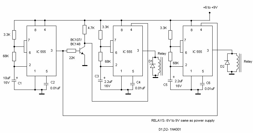
This circuit uses three easily available 555 timer ICs. All three work as astable multivibrators. The first 555 has an on period and off period equal to 1 sec. This IC controls the on/ off periods of the other 2 555s which are used to flash two bulbs through the relay contacts.
The flashing occurs at a rate of 4 flashes per second.
The diodes are used to protect the 555 ICs from peaks. The relays should have an impedance greater than 50ohms i.e, they should not draw a current more than 200mA.
The flashing sequence is as follows:
The bulb(s) connected to the first relay flashes for about 1 sec at a rate of 4 flashes per second. Then the bulb(s) connected to the second relay flashes for 1 sec at a rate of 4 flashes per second. Then the cycle repeats.
The flashing rates can be varied by changing the capacitors C3 and C5. A higher value gives a lower flashing rate.
Note that the values of C3 and C5 should be equal and should be less than that of C1.
The value of C1 controls the change-over rate ( default 1sec). A higher value gives a lower change-over rate.
If you use the normally open contacts of the relay, on bulb will be OFF while other is flashing,and vice versa.
If normally closed contacts are used, one bulb will be ON while the other is flashing.
Dancing lights
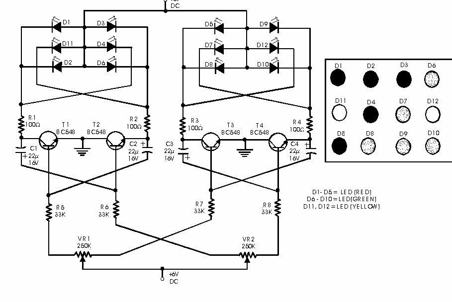
Here is a simple circuit which can be used for decoration purposes or as an indicator. Flashing or dancing speed of LEDs can be adjusted and various dancing patterns of lights can be formed.
The circuit consists of two astable multivibrators. One multivibrator is formed by transistors T1 and T2 while the other astable multivibrator is formed by T3 and T4. Duty cycle of each multivibrator can be varied by changing RC time constant. This can be done through potentiometers VR1 and VR2 to produce different dancing pattern of LEDs. Total cost of this circuit is of the order of Rs 30 only. Potentiometers can be replaced by light dependent resistors so that dancing of LEDs will depend upon the surrounding light intensity. The colour LEDs may be arranged as shown in the Figure
The circuit consists of two astable multivibrators. One multivibrator is formed by transistors T1 and T2 while the other astable multivibrator is formed by T3 and T4. Duty cycle of each multivibrator can be varied by changing RC time constant. This can be done through potentiometers VR1 and VR2 to produce different dancing pattern of LEDs. Total cost of this circuit is of the order of Rs 30 only. Potentiometers can be replaced by light dependent resistors so that dancing of LEDs will depend upon the surrounding light intensity. The colour LEDs may be arranged as shown in the Figure
Simple variable frequency oscilator circuit.
This is a very simple circuit utilising a 555 timer IC to generate square wave of frequency that can be adjusted by a potentiometer.
With values given the frequency can be adjusted from a few Hz to several Khz.
To get very low frequencies replace the 0.01uF capacitor with a higher value.
To get very low frequencies replace the 0.01uF capacitor with a higher value.
The formula to calculate the frequency is given by:
1/f = 0.69 * C * ( R1 + 2*R2)
The duty cycle is given by:
The duty cycle is given by:
% duty cycle = 100*(R1+R2)/(R1+ 2*R2)
In order to ensure a 50% (approx.) duty ratio, R1 should be very small when compared to R2. But R1 should be no smaller than 1K.
A good choice would be, R1 in kilohms and R2 in megaohms. You can then select C to fix the range of frequencies.
A good choice would be, R1 in kilohms and R2 in megaohms. You can then select C to fix the range of frequencies.

Electronic Siren
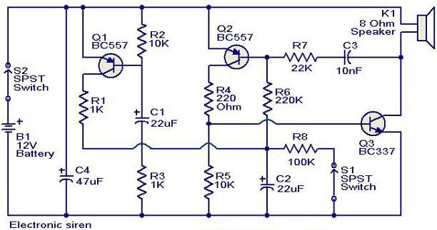
This is a compact electronic siren circuit based on three transistors.This circuit is suitable for in corporating with other alarm or siren projects such as burglar alarms, automatic factory sirens etc or a simple push to on alarm.
The electronic siren circuit given here is based on a complementary transistor pair consisting of Q2 & Q3 (BC557 & BC 37) wired as an astable multivibrator oscillator,which directly drives the speaker.The transistor Q1 is used to provide a full charge on capacitor C2 when power is turned ON. When push button switch S1 is pressed , the capacitor C2 slowly discharges through resistor R8.This makes the circuit to oscillate at a low frequency that increases to a high frequency and kept indefinitely as the capacitor is fully discharged. When the switch P1 is released, the output frequency decreases slowly as C2 is charged to the positive voltage through resistance R6 and the Base-Emitter junction of tramsistor Q2. When C2 is fully charged to the positive battery voltage the circuit stops oscillating.
Led matrix
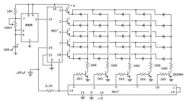
The circuit below illustrates using a 10x10 matrix to sequence up to 100 LEDs with just three ICs and 20 transistors. The two 4017 decade counters control the 10 rows and 10 columns so that one LED is selected depending on the output of the decade counters.
The LED circuit is drawn showing 25 LEDs and 10 transistors (2N3904) but can be expanded up to a 100 by using sucessive stages of the 4017 counters.
For example, to expand the circuit to 60 LEDs for displaying minutes or seconds of a clock, the rows counter could be reset from pin 12 (carry out) rather than pin 1 as shown, and the columns counter will be reset from pin 5 rather than pin 1 as shown. And then add transistors to pins 1,5,6,9,and 11 of the rows counter and pin 1 of the columns counter. Take a look at the "10 Stage LED Sequencer" for a listing of all the connections of the 4017 decade counter.
Random flash
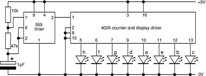
This project flashes eight LEDs in an apparently random manner. It uses a 4060 combined counter and display driver IC which is designed for driving 7-segment LED displays. The sequence is not really random because seven of the LEDs would normally be the display segments, the eighth LED is driven by an output that is normally used for driving further counters. The table below shows the sequence for the LEDs. You can use less than eight LEDs if you wish and the table may help you decide which ones to use for your purpose.
www.budgetronics.eu
www.budgetronics.nl
www.budgetronics.mobi
www.budgetronics.tel
www.budgetronics.be
www.budgetronics.net
www.budgetronics.org
www.budgetronics.me
www.budgetronics.asia